Last Updated June 6th 2018
Flow Control Module
- Flow Control Module
Introduction
As you may already know, the purpose of this project is (in short) to develop a method of controlling water flow rate depending on light intensity levels (there is a lot more to it than this - see the overview). The flow rate module (as the name might suggest) is an integral sub-module which modules flow rate dependent on some input.
The purpose of this document is two-fold; not only should it aid you in understanding and using the final implementation that we chose for this sub-module but also details the design process to understand the reasoning behind the decisions that we made.
The Design Process
Technical Specification
The first step undertaken was to draw up a detailed technical specification. The following specification is intended to be solution neutral.
Requirements
| Requirement Type | Requirement | Comments |
|---|---|---|
| Functionality | The system must be fail-safe. | In the absence of power, there must be zero flow. This is essential for safety. |
| Functionality | The system must be able to modulate flow rate dependent on some form of input signal. | Signal form unspecified. |
| Functionality | The system must be able to cope with flow rates up to 6 L/hour. | Given by the Majico photocatalyst flow rate. |
| Usability | The system must be able to operate in varying sunlight levels. | For example, for an electrical system, this requirement means that the system must accept a range of input voltages (6V-25V D.C. e.g. from a solar panel). |
| Usability | The system must be compatible with a range of water supply pressures. | - |
| Reliability | The system must be able to operate in temperatures between between 0°C and 60°C. | This gives a marginal around typical temperatures in Tanzania. |
| Reliability | The system must be resistant to rain. | There is a monsoon season in Tanzania! |
| Supportability | The system should be easily repairable if there is component failure. | - |
| Supportability | The system should allow for easy circuit board replacement. | In case of component failure. This requirement mainly relates to an enclosure for such a system. |
Brainstorming
How can we control the flow?
The key decision to make is how to module the flow of fluid. Two possible methods of controlling flow rate are outlined below.
Active Control
Fluid can be kept in a reservoir and pumped directly to another location.Advantages:
- Fail-safe. Without power, fluid is unable to flow (assuming the flow is initially at rest).
Direct control over fluid flow rate - the flow rate is entirely controlled by the pump input and the fluid properties.
Disadvantages:
- High power consumption.
Passive Control
If fluid is already flowing, its flow can be hindered or slowed down in order to control the flow rate e.g. by moving a plate across a pipe.Advantages:
- Energy is not expended in moving fluid. It is easy to create fluid flow (e.g. by holding a reservoir at a height) and thus energy expenditure on movement is wasteful.
Easy to create/find (e.g. spring-loaded) systems that are closed when there is no power input and are thus fail-safe.
Disadvantages:
- Need to account for possible accumulation of fluid at the valve input.
- Need fluid flow.
No direct control over instantaneous fluid velocity/flow rate.
This method lends itself better to purely mechanical solutions compared to active control. For example, a block of material could expand when heated (suggesting the presence of sunlight) and then block flow rate through a bypass pipe (thus perhaps increasing the flow rate through another pipe). However, at this stage of the design, an electrical approach had already been chosen.
So why use a valve?
Given that it is very easy to create a fluid flow by holding fluid in an elevated reservoir and that fail-safe solenoid valves are readily available, it was decided that this form of flow control would be appropriate for this project.
Powering the valve
Common microcontrollers are very limited in the currents that they are able to supply through their GPIO (general purpose input-output) pins. For example, the Arduino Uno has a maximum D.C. current of 20 mA per I/O (input/output) pin corresponding to a maximum power of 0.1 W (at 5V) (Technical Specs Here). Typical valves have power draws at least an order of magnitude greater than this and thus additional circuitry is required to allow the microcontroller to interface with components which require much high currents.
A simple way of performing this interfacing is to use a H-Bridge which is commonly used for bi-directional control of motors. These components are available as a standard package (the L298P is common) and these packages provide additional advantages over using a transistor current amplifier such as overtemperature protection. These packages are very often used with common hobby microcontrollers (e.g. Arduinos) and this is one of the reasons we chosen them.
Interfacing with other modules
The valve must be controlled using the control submodule (documentation here). H-Bridges require digital inputs in order to control their outputs; that's to say, if the voltage is above a certain threshold (dependent on the specific H-Bridge used), it is considered to be on. Thus GPIO pins from this module can be connected directly to the input pins of any H-Bridge input (especially because distances between these modules are unlikely to be particularly large). Note that some H-Bridges require a logic voltage input (typically around 5V, used to power logic circuits) and this can come directly from the control module whilst the high voltage supply is provided using a separate, high voltage rail.
Design Summary
In summary, the key aspects of the system designed are:
- The flow will be modulated using a solenoid valve.
- A H-Bridge will allow the control module to interface with the flow-control module.
Our Implementation
After our design process, we were ready to implement our design. Please note that schematics and PCB layouts were designed using KiCad which is open source! The GitHub repository for the flow control module is found here and contains:
- Schematics (i.e. how each component connects to each other).
- PCB (printed circuit board) layout.
- Additional Gerber and drill files required for PCB manufacture.
Please note that footprint and component files (or libraries, using KiCad terminology) will be required to modify files in the GitHub repository; these can be found in our parts library repository here.
The Schematic
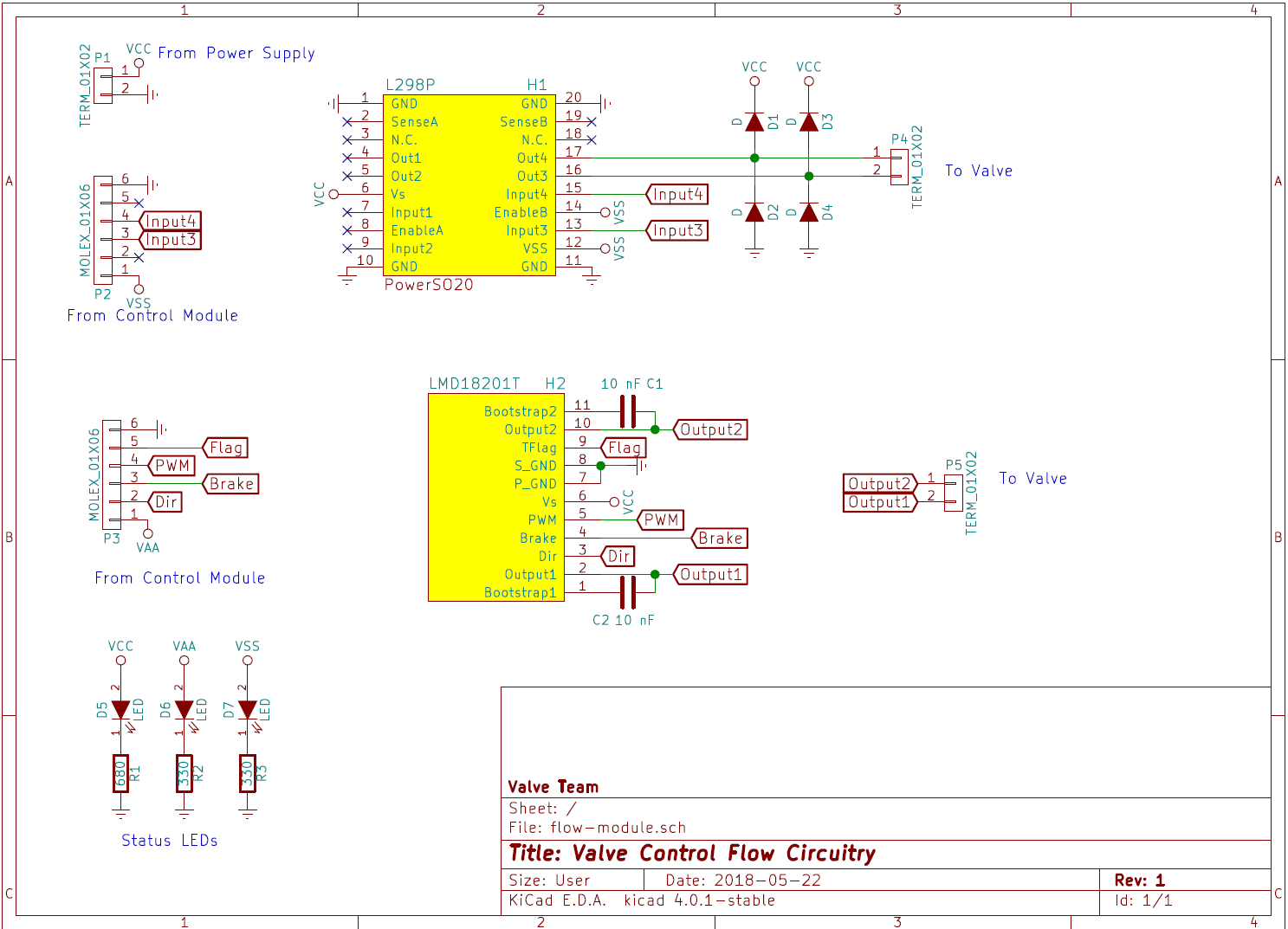
The schematic above shows the connections between different components within for the PCB. Note that:
- There are two different H-Bridge chips; the
L298P(click for the datasheet) is a standard part, commonly used for hobby electronics and is fairly cheap.LMD18021Twhich is about twice the price of theL298Pbut is more robust in terms of the input voltages it accepts and incorporates some advanced features such as a thermal flag output. Both were placed on the same board to allow each to be tested simultaneously. For each, a terminal block connects the output to the solenoid valve. - A terminal block is used to connect the circuit to the power supply.
- 6-Pin Molex KK connectors are used to interface between the flow control module and the control module.
- There are three indicator LEDs; one to show power from the main power supply (e.g. a solar panel), the other two indicate which H-Bridge chip is being used.
The PCB
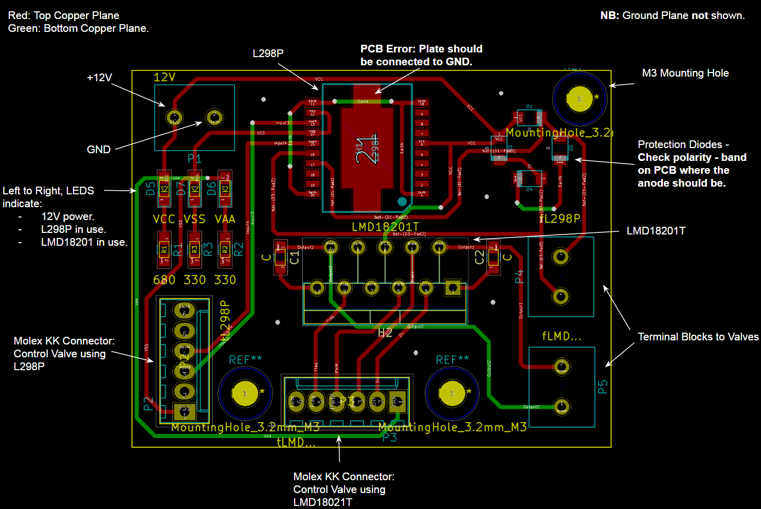
The image above shows the PCB layout. Please note the following:
- Ground planes are not shown.
- The dimensions of the circuit board are 59 by 47 mm.
- The terminal block connecting the PCB to the main power supply is in the top left of the board.
- The terminal blocks connecting the PCB to each solenoid valve are on the left of the board. The valves do not have a polarity and thus can be connected either way around.
- There is an error with this PCB - the ground pad of the L298P chip should be connected to the ground plane but it is not.
- In our implementation, each of the status LEDs has been given a different colour.
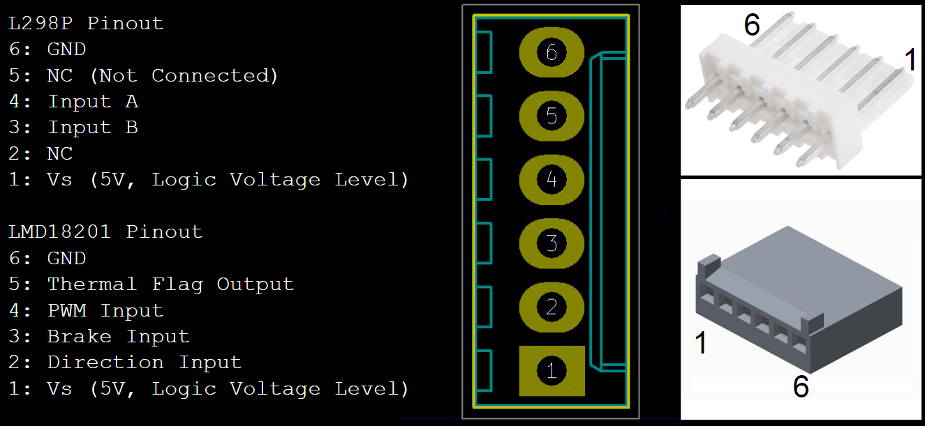
The diagram above shows how the Molex KK connectors should be interfaced with other components. Molex KK diagrams reproduced from MRO Electronics and RS.
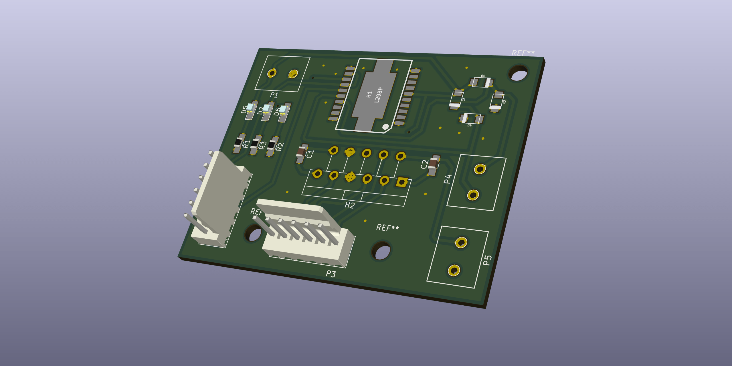
The 3D Model
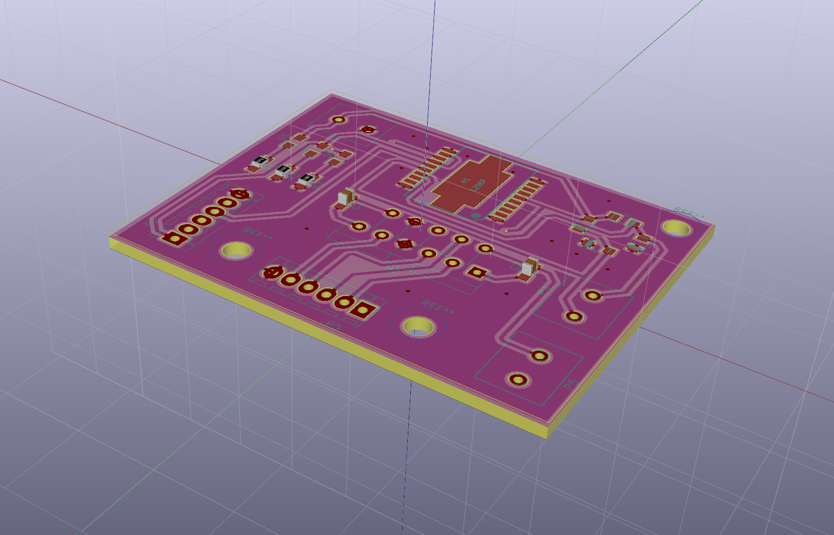
The diagram above shows a 3D model of the PCB.
The Valves
Two off-the-shelf solenoid valves were used with the above PCB:
- Adafruit Solenoid Valve. This valve has a minimum pressure requirement of 0.03 MP and liquid can only flow in one direction.
- RS Hydralectic Solenoid Valve. This has a higher minimum pressure requirement but is unidirectional.
The valve operating flow rates are well above the maximum photocatalyst flow rate (around 6 L/hour).
Any solenoid valve can be used with the above PCB.
Controlling the Valves
In order to control the valves using the H-Bridges on the PCB, the required inputs must be understood. Correct connections must first be ensured (according to the Molex KK pinout diagram).
L298P
The L298P requires two digital inputs; input A and input B which are considered to be on if the voltage on the pins exceed 2.3V. There are no additional inputs or outputs. Thus the output of the solenoid valve can be controlled as follows.
| Input A | Input B | Valve State |
|---|---|---|
| Low | Low | Closed |
| High | Low | Open |
| Low | High | Open |
| High | High | Closed |
Note that if both inputs are the same voltage, the valve is held closed electrically (similar to a 'brake' mode). This actually consumes power and could be optimised by 'disabling' the H-Bridge when no output is required - more on this later.
LMD18201
The control using the LMD18201 component is different. There are three digital inputs which are considered to be high when their voltage exceeds 2V. There is also an additional output - a thermal flag.
| Pin | Input / Output? | Comments |
|---|---|---|
| Brake | Input | If the output is a motor, the motor will brake if the input is high by shorting the terminals. This is not useful behaviour for a solenoid valve and thus this input should be held low i.e. connected to GND. |
| Direction | Input | This pin controls the direction of current flow between output pin 1 and 2. The valves are not polarised and thus the value of this pin is not important. |
| PWM | High | When this input is high, the solenoid valve is open. Otherwise, it is closed. |
| Thermal Flag | Output | This output is normally high. However, when the 'junction temperature' exceeds 145°C the output becomes low. This can be used by the control module. |
Bill of Materials
The bill of materials for the prototype implemented is as follows. Note that component links are clickable to see where the component was purchased from.
| Component | Value | Quantity | Unit Price (£) | Total Price (£) |
|---|---|---|---|---|
| Unpolarised Capacitor | 10 nF | 2 | 0.08 | 0.16 |
| Diodes | - | 4 | 0.26 | 1.03 |
| LEDs | - | 3 | 0.48 | 1.45 |
| L298P (H-Bridge) | - | 1 | 4.97 | 4.97 |
| LMD18201 (H-Bridge) | - | - | 12.16 | 12.16 |
| Molex Connectors | 01x06 | 2 | 0.27 | 1.54 |
| Terminal Blocks | 01x02 | 3 | 0.45 | 1.35 |
| Resistor | 300 Ω (instead of 330 Ω) | 2 | 0.11 | 0.22 |
| Resistor | 680 Ω | 1 | 0.03 | 0.03 |
| (RS) Hydraelectric Solenoid Valve | - | 1 | 12.46 | 12.46 |
| Adafruit Solenoid Valve | - | 1 | 7.22 | 7.22 |
| Total | | | | 41.59 |
Testing Results
Valve Testing
Multiple valves were ordered to determine their suitability. An experiment was performed where each valve was connected directly to a power supply and the input voltage was varied. The results of this experiment were found below.
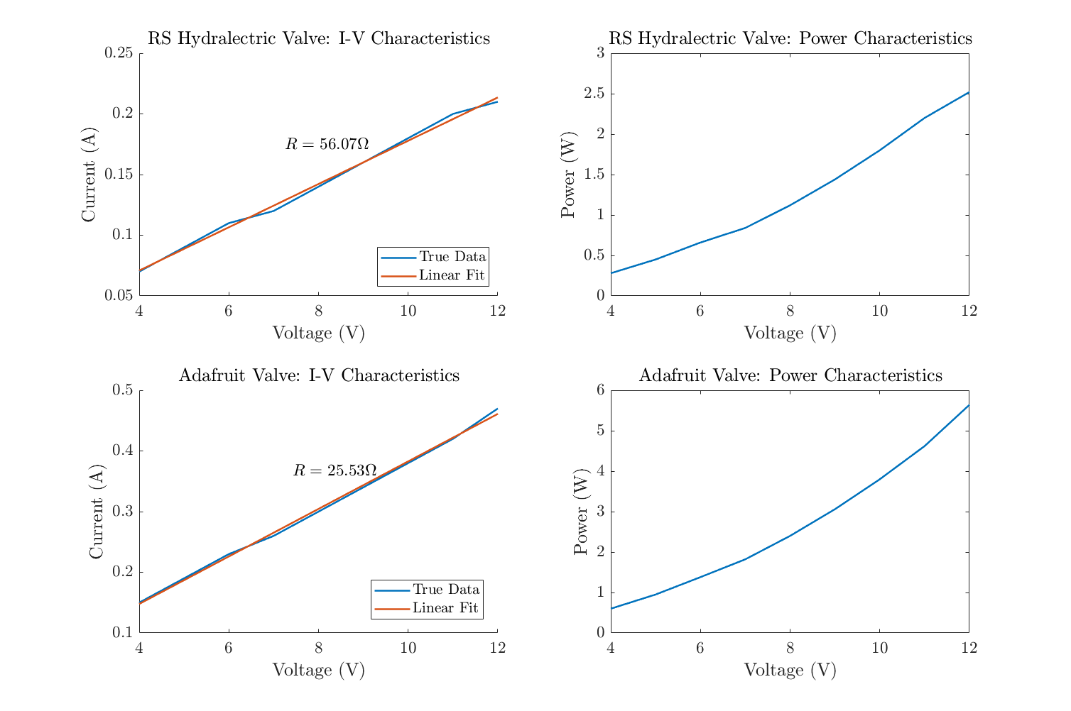
The key findings of this experiment are that:
- The power draw is determined by the ohmic (real) part of the solenoid resistance, suspected to be characterised by the resistance of the inductor coils. The resistance of the Adafruit valve is smaller and thus when a fixed voltage is applied across the terminal ends, the power draw is higher (since P = V2/R).
- The RS Hydraelectric valve is able to actuate at voltages exceeding 4V whilst the Adafruit valve actuates at voltages exceeding 5V.
- The Adafruit valve requires a lower pressure in order to drive flow through the valve (this was determined heuristically by attempting to push air through each valve).
- As the voltage applied to the valve increases, the power draw increases without conferring any significant advantage. Therefore, it may be advantageous to step down the input voltage into the valve to reduce power consumption. This will still require a H-Bridge driver due to the high currents involved.
H-Bridge Testing
The power draw of each H-Bridge when idle and when powering the valve was determined (the power draw of each valve at a given voltage can be determined by using the results of the previous experiment). Please see this spreadsheet for more details of the calculations.
The power draw of both H-bridges when idle is around 0.24 W - due to the circuitry implemented, it is difficult to determine which H-Bridge is consuming more energy. However, it was discovered that the L298P was faulty and thus an alternative H-Bridge was used to calculate these powers. It is assumed (naively) that the idle H-Bridge draw is the same for each package in order to calculate the power requirement for all the additional circuitry of the alternative circuit.
The conclusions of this experiment were:
- The idle power draw of each H-Bridge is fairly small, estimated to be approximately 120 mW.
- The additional power expended in the
L298Pwhen the valve is open is 0.77W whilst this figure is 0.35W for theLMD18201. The voltage at the solenoid valve output is lower for the
L298Pthan theLMD18201(9.9V v.s. 12V). As a result, even though the valve is fully open in each case and the power draw of the H-Bridge circuit is higher for theL298P, the total power draw is lower for this chip (5.04W v.s. 5.64W). Give that theL298Pis much cheaper than theLMD18201, it may be a better option - more on this in the next section.Recommendations
Refining Our Design
The design and implementation produced worked well for our purposes. If the board were to be redesigned for the final product, the following changes would be made:
Ditch the H-Bridge! Even the cheaper H-Bridge above can cost about £3.00. The key advantage with a H-Bridge is bi-directional control but this is not advantageous. This could be replaced with a MOSFET and protection diode which can reduce to the cost to about 40p. There is good documentation and resources for this online e.g. this StackExchange article is exactly the use case here.
Change the
L298Ppackage used; the surface mount package used (PowerSO20) was difficult to solder (due to the ground plane). A through-hole package can be found and is cheaper (e.g. here).The main board can be incorporated into the main control module board since the solenoid valve is operated at a distance using wires. This reduces the amount of wiring involved and could reduce the overall PCB size, decreasing the cost of manufacturing PCBs.
Decrease the PCB size as much as possible. If the entire PCB is to be replaced if faulty, keeping pins accessible is less of a concern.
Include a voltage regulator which steps down the high-voltage rail. It is easy to reduce the power consumption by a significant amount by actuating the valve using 6V rather than 12V. However, in choosing the amount of voltage to step down to, the voltage lost due to the H-Bridge must be taken into account (as the voltage across the valve terminals must be sufficiently large to actuate the valve). For example, if the
L298Pis to be used, an 8V power voltage regulator is appropriate and is not too expensive (e.g. around £1.10 here). Since the valve will be controlled quite slowly, the decrease in response time is not a significant problem.
Choosing Your Own Components
For this submodule, there are two main components to be chosen. This section will give brief guidelines as to how to choose each of the components.
Choosing a H-Bridge
In general, the factors to consider when choosing a H-Bridge (in what we believe to be decreasing priority) are:
Cost: the cost of the H-Bridge contributes significantly to the cost of this submodule and the overall project. Reducing costs even by small amounts can give significant gains if large quantities are produced.
Component Availability: if components are available in Tanzania (where initial testing for this will begin), significant savings may be may in import and shipping costs, affecting the overall cost of the module.
Power draw: the power draws between lower end and higher end H-Bridges does not differ a large amount. Thus this is a low priority though having a low power draw remains advantageous.
Additional features: advanced H-Bridges include additional features such as a thermal flag. These features are unlikely to be needed in most cases but may be useful.
However, why use a H-Bridge in the first place? As mentioned in the previous section, a MOSFET and diode can be used for a far lower cost. If this is taken, the MOSFET must be chosen such that:
- The MOSFET full activates when the microcontroller output pin is high i.e. the gate threshold voltage should exceed the microcontroller output voltage.
- The MOSFET is able to function with a high voltage power supply.
- The MOSFET is able to provide sufficient current to the valve (this is on the order of 0.5 A).
- The MOSFET resistance (Rds) is sufficiently low so that it doesn't become too warm, perhaps less than 0.1 Ω.
Note: above recommendations drawn from this StackExchange article which should provide a good place to start!
Choosing a Valve
The factors to be considered when choosing/designing a solenoid valve (in what we believe to be decreasing priority) are:
Cost: the cost of the H-Bridge contributes significantly to the cost of this submodule and the overall project. Reducing costs even by small amounts can give significant gains if large quantities are produced.
Component Availability: if components are available in Tanzania (where initial testing for this will begin), significant savings may be may in import and shipping costs, affecting the overall cost of the module.
Water pressure requirements: different valves require different water pressures to be reliable. A worthwhile test to run is to find the pressure input required to give the maximal flow-rate through the photocatalyst, 6 L/hour. It would then be useful to convert this into a height at which the water reservoir must be held and to check whether this is reasonable.
Power draw: the power draws can vary significantly between valves and must be matched well to the solar panel to be used.
That's all from me!
Feel free to get in touch if you have any more questions!