Last Updated June 6th 2018
The Overall System
Introduction
Hi there. If you are looking for a brief overview of our solar controlled valve, you are in the right place!
Just a quick recap: access to drinking water is a major problem in the world. 844 million people don't have access to clean water and 31% of schools don't either (WaterAid). Clearly, this isn't okay but Majico have developed a way of solving this - passing water over a photocatalyst to purify it and make it safe to drink. But there is a problem - the time that the photocatalyst takes to act on the water depends on the light level and thus some method of modulating flow rate dependant on the light level is required. To solve this, we have developed a light controlled valve.
The purpose of this document is to provide a brief overview of the system to understand the overall function. We also include necessarily steps to make the final product and give a rough idea of cost.
Key Requirements
A full specification was drawn for this project; this can be found here. The key points from this document to note are:
The system must be fail-safe. In the absence of light or if anything else goes wrong there should be no flow.
The flow control should not be binary. The photocatalyst doesn't either work if there is enough light and not work if there isn't enough light! In reality, there is a gradual chang in efficiency (and thus maximum flow rate over the photocatalyst) as the light levels vary. The solution should thus give a gradual (ideally linear) response between flow rate and light intensity.
Adding to the above point, there are also lower and upper light intensity thresholds below which no flow is desired and above which the flow rate should not be increased. However, the exact values for these thresholds may depend on the photocatalyst area, final reaction design, e.t.c. There are a number of unknown factors and thus these thresholds must not be set but rather be tunable by the operator.
Solution Overview
The approach we took for this problem is to use solar power, favouring an electrical approach over a mechanical approach; the mix of tunability requirements and an (ideally) linear response ruled out a mechanical approach.
Note: whilst the final product is to be powered using solar power, our prototype was only tested using a bench power supply and designed to be robust (i.e. accept a wide range of input voltages).
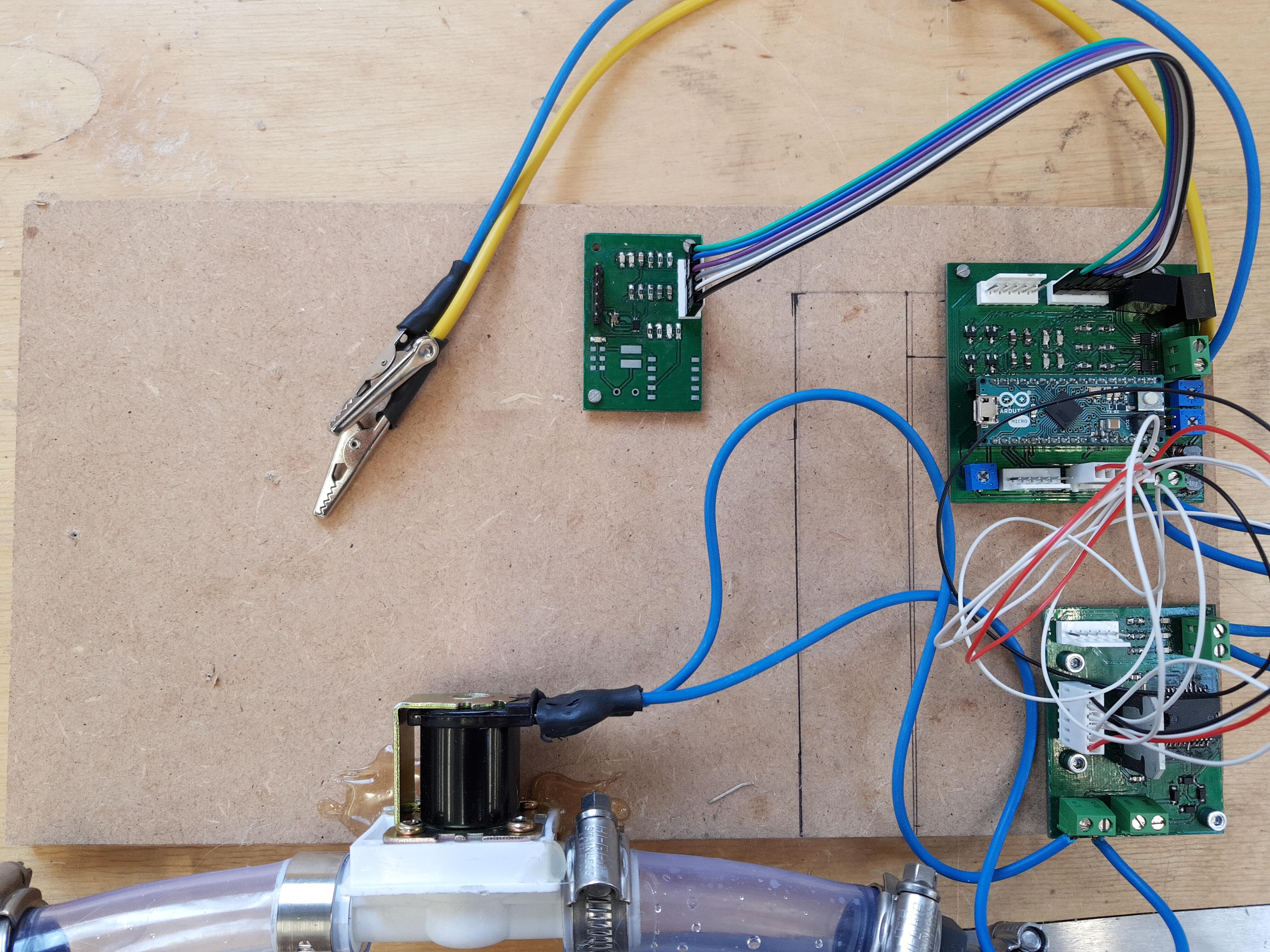
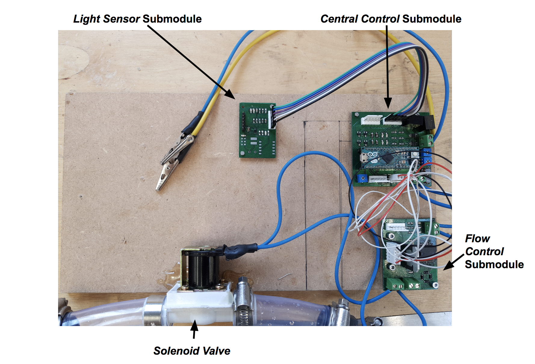
The final prototype we made consists of the following components.
- The central control submodule which reads external sensors and sends out signals. Find out more...
- The light sensor submodule which detects light intensity. Find out more...
- The flow control submodule which modulates flow rate dependent on an electrical input signal. Here, we used a solenoid valve. Find out more...
The image below shows the final prototype that we made.
Power Draw Calculations
By looking at the datasheets for components used within the three submodules above, absolute maximum power ratings for key components were found and used to calculate an expected peak power draw.
Items consuming significant power are:
- Microcontroller (Arduino Micro): (maximum rating of) 1 W.
- Solenoid Valve: 4 W (Note: this is the cheaper Adafruit valve - see the flow control documentation for more information).
- H-Bridge / Valve Driver circuitry: (maximum rating of) approx 1.1 W.
- 10 LEDs: 0.6 W.
This gives a peak power draw of 7 W. When testing, we found the peak power draw to be 6.12 W, verifying the above calculations. These calculations are (intentionally) an overestimate since the absolute maximum ratings were used.
These numbers might not have much meaning to you; the key thing here is that 10W solar panels (more than enough to power our system) are readily available and cost around £25.00 e.g. here.
Another point: whilst power consumption was considered by all team members, it was by no means optimised for in the prototype made. Significant power savings could be made by optimising component choice and other techniques (e.g. stepping down the valve driving voltage could give a significant saving, see here).
From Prototype to Final Design
In order to go from the prototype to a final design, a number of steps need to be taken.
Evaluation of Modularity.
Our prototype was designed in three distinct parts and subsequently, three separate printed circuit boards were manufactured. Modularity in design worked well, allowing isolation of component failure and effective teamwork. However, for the final design the flow control and central control submodules can certainly be incorporated into one PCB. This has the advantages of reducing cost (as an estimate, we suspect that removing the connectors and wires and the subsequent reduction in board area will reduce the cost by about £4). Furthermore, it reduces the number of points of failure - poor connections can often lead to reliability issues. However, this would increase the cost of board replacements (since a larger PCB would have to be replaced when earlier only one would have to be). Incremental improvements are also made more difficult.
Understand Solar Power.
Even though our systems have been designed to be robust with regards to input voltage, there are a number of unknowns that need to be investigated.
What timescales over which does the power/voltage output of the solar panel change? For example, if the solar panel is momentarily obstructed, how quickly does the output voltage fall? This is a pertinent question since such obstructions are likely in actual use (e.g. vehicles driving past, human walking past).
What effect does an intermittent power supply have on the lifetime of electronic components? An area of particular concern is the microcontroller used - not only could its lifetime be greatly reduced but if the microcontroller becomes damaged, what happens to the valve output? The answers to these questions are currently unknown.
Once these unknowns have been characterised through intensive testing, a decision must be made on whether to power the system directly using a solar panel or to use the panel to charge a battery.
Understand the constraints.
The constraints which bind a design are crucial for appropriate design decisions and component choice and the constraints should be better characterised. It was thought that power draw was the most significant constraint but the power draw calculations above suggest that this may not be the case. So is cost the most significant constraint? By better understanding the constraints, a better final design can be produced.
The recommendations made in the documentation of each sub-module should be reviewed and incorporated if appropriate.
Remove redundancy and finalise component choice.
Rough Costings
Even though a final proposal is by no means set in stone at this stage, a rough idea of costings may be informative. Using similar components to our prototype but optimising (somewhat) for cost, we find that an approximate total cost is £45.00 + VAT. Significant items of expenditure are:
- PCB Manufacturing (£15.00 - could be reduced by £3.50 by combining the flow control and the central control submodules).
- Solenoid Valve (£8.00).
- Microcontroller (£3.32).
- Voltage Regulators (£5.50).
(Prices exclude VAT)
We believe that this cost could certainly be reduced by more careful component choice and manufacturing certain components e.g. the valve. Note that the cost of a solar panel (or battery and charge controller if required) have not been included above.
Closing Comments
That's it! Hopefully, you found this document helpful and informative.
If you want to contribute, the next steps would be to take a look through some of the individual submodule documentation (which is far more detailed) and check out our GitHub repository!. There are a number of questions that remain open - if you have any pointers (or data) on these questions, we would really appreciate it!
Feel free to send any one of the team an email if you have any queries.