Last Updated June 7th 2018
Light Module
- Technical Specification
- Brainstorming
- Schematic
- PCB Design
- PCB Rendering
- Procurement Issues
- Light Sensor Devices
- Design Parts List
- Component Selection
- Bill of Materials
Introduction
At a high level, the purpose of the project is to develop a method of controlling water flow in response to varying ambient light intensities. The light sensor module is an independent sub-module of this overall system that is responsible for measuring the ambient light intensity and communicating the measured light intensity to the central control module.
The following documents the design process and chosen implementation for this module, and should enable the reader to undertake further development on this module or to use the device in the field.
Design
Our overall design approach followed a modularisation of the solution into three components: the light sensor module that this document describes, the flow module and the central control hub. Specifications drawn up for the central control module in particular placed constraints on the design of this module.
Technical Specification
A brief technical specification was drawn up to qualify the requirements this sub-module had to meet in order to successfully fulfil its purpose. The following specification is intended to be solution neutral, and splits requirements into five groups: functionality, usability, reliability, supportability and performance.
| Requirement Type | Requirement Number | Requirement | Comments |
|---|---|---|---|
| Functionality | LM.FR.01 | The system must detect the intensity of ambient light. | The system must have some means to measure the ambient light level, which should give an indication of how effective the photocatalyst in the Majico system is at a given time. |
| Functionality | LM.FR.02 | The system must communicate the intensity of ambient light over a digital interface. | The separation of the light sensor module from the central control board was an unknown, but could be in the order of a metre. |
| Functionality | LM.FR.03 | The system should communicate the intensity of ambient light over an I2C interface. | An I2C interface suits our application slightly better of the essentially two communication standards available. |
| Usability | LM.UR.01 | The system must accept a 6V-25V (DC) range of voltages as a supply voltage. | A solar panel could provide a voltage from 6V-25V DC. |
| Reliability | LM.RR.01 | The system should continue accurately reporting light intensity after a drop and recovery in power supply. | The light falling on a solar panel powering the system could stop at any time, and power no longer be provided to the module. Any devices used should be able to cope with power drops of this nature. |
| Reliability | LM.RR.02 | The system should be operational in temperatures between 0-60°C. | This gives a margin around typical temperatures in Tanzania, in case the temperature rises inside the enclosure or heat is produced by electronic components. |
| Reliability | LM.RR.03 | The system should have an enclosure that protects the electronics from rain water. | There is a monsoon season in Tanzania. |
| Performance | LM.PR.01 | The system must measure light intensity in the 350-650nm range. | The photocatalyst responds to light in the 200-650nm range, but the PET enclosure would mean only 350-650nm wavelengths would reach the catalyst itself. |
| Supportability | LM.SR.01 | The system must allow for the circuit board to be replaced without having to replace any interfacing wiring looms or other interface circuitry. | - |
| Supportability | LM.SR.02 | The system must allow for the circuit board to be replaced without having to replace the enclosure. | - |
Requirements LM.FR.02 and LM.FR.03 for example look out of place out of context. Knowing that an Arduino was to be chosen as a microcontroller, this imposed a constraint on the interface between the light sensor module and the control module. An analogue interface was seen to not be robust enough, particularly over the expected separations of around 1 metre. This dictated a digital interface, and the Arduino narrowed the choice to I2C or SPI. It was decided that I2C would be preferred for this module - fewer wires are required and we wouldn't need the extra speed that SPI affords. I2C clock stretching also provided interesting potential.
Brainstorming
The central concern when brainstorming and selecting components for this module was the wavelength response. Many digital light sensor chips have low or zero responsivity below 450nm. However, some of the requirements imposed by the above specification making component selection difficult. The devices used have to be robust to drops on power, which isn't easily quantified from component datasheets. Two or more light sensor devices should be integrated into the board so a comparison can be made on these sorts of metrics.
Implementation
A circuit schematic and PCB layout were designed to implement the design. KiCad was used as an electronics design tool for this implementation, which is open source and is well supported in the Engineering Department, but Autodesk EAGLE would have been equally appropriate. The GitHub repository containing the KiCad schematic, PCB layout and Gerber/drill (needed for manufacture) files can be found here.
Additional footprints and components for schematics were created for some of the parts used across our three sub-modules. These will be required to modify the lighting module's KiCad design files; these can be found in our parts library repository here.
Schematic
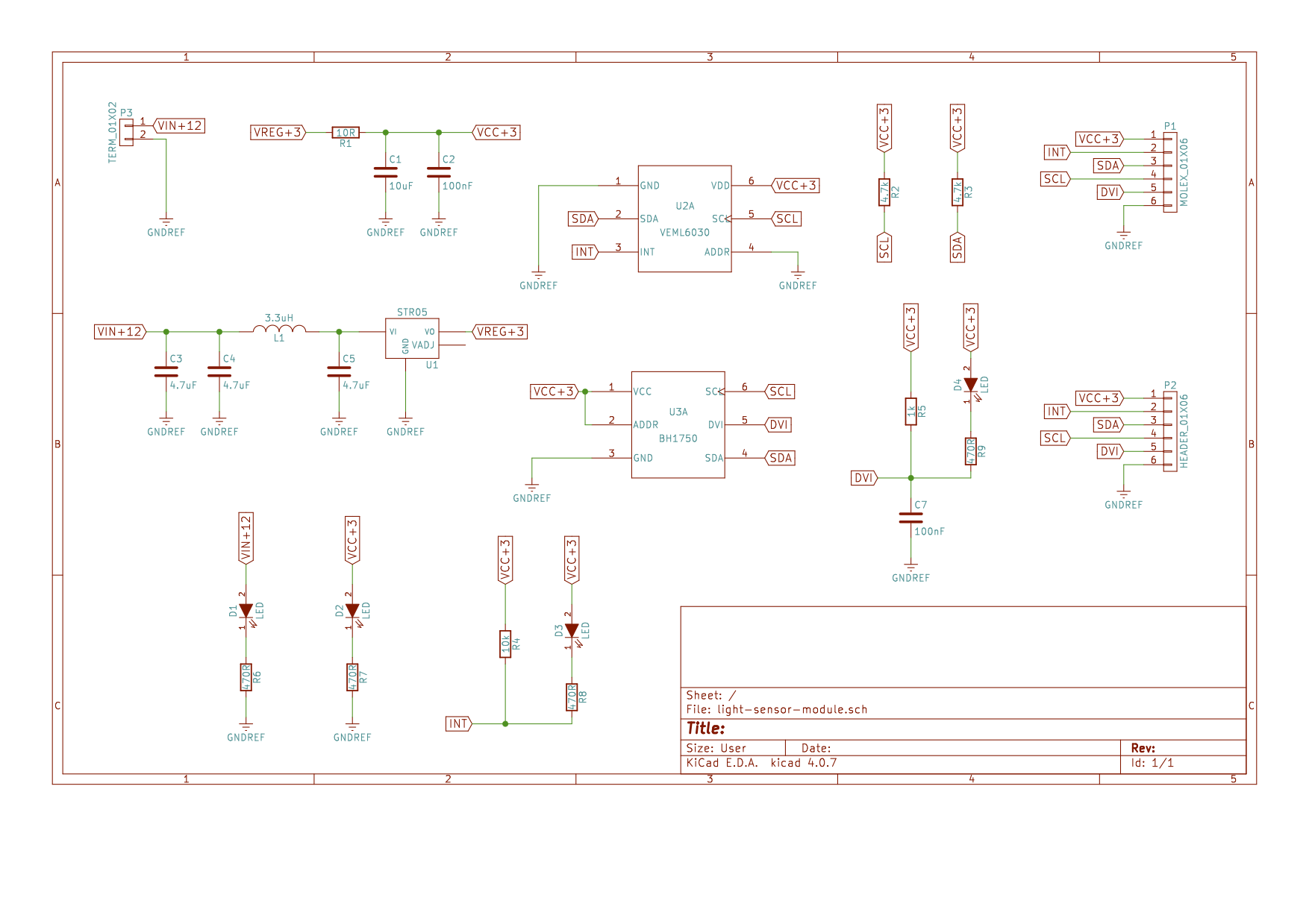
The schematic above shows the circuit design for the light sensor module. There are two different light sensor devices on-board: the BH1750 and the VEML6030. Discussion of the choice of light sensor modules will follow. A terminal block is used to connect the circuit to a DC power supply or solar panel. A 6-pin Molex KK connector provides a header for a wiring loom to interface the central control module and the light sensor module. A 6-pin 2.54mm header was also integrated that matches the pin-out of the Molex header for testing/debugging. Four indicator LEDs are present, two to indicate the presence of power supply voltages and two to indicate the use of one of the light sensor devices' interrupt pins.
This module was designed to be equipped with a STR series switching voltage regulator to regulate the 12V supply to the 3.3V supply required by both light sensor devices. The 3.3V supply can also be provided externally via the Molex header, a flexibility feature that was of great use when supply problems inhibited our ability to source the STR series regulator part. A filter was designed upstream of the switching regulator according to the STR series datasheet to smooth the input supply, which makes that sub-circuit more robust for an eventual solar panel input.
PCB Design
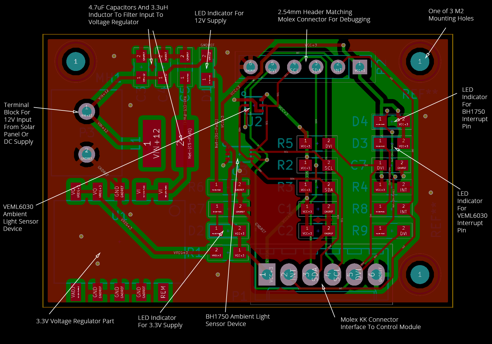
The above diagram shows an annotated copy of the PCB layout, with all the major components discussed in the previous sub-section pointed out. Our LEDs were chosen to be orange for 12V and green for the main 3.3V supply rail; a common standard used across our sub-systems. Yellow and blue were chosen for the status LEDs indicating the use of the interrupt pins for the VEML6030 and BH1750 respectively.
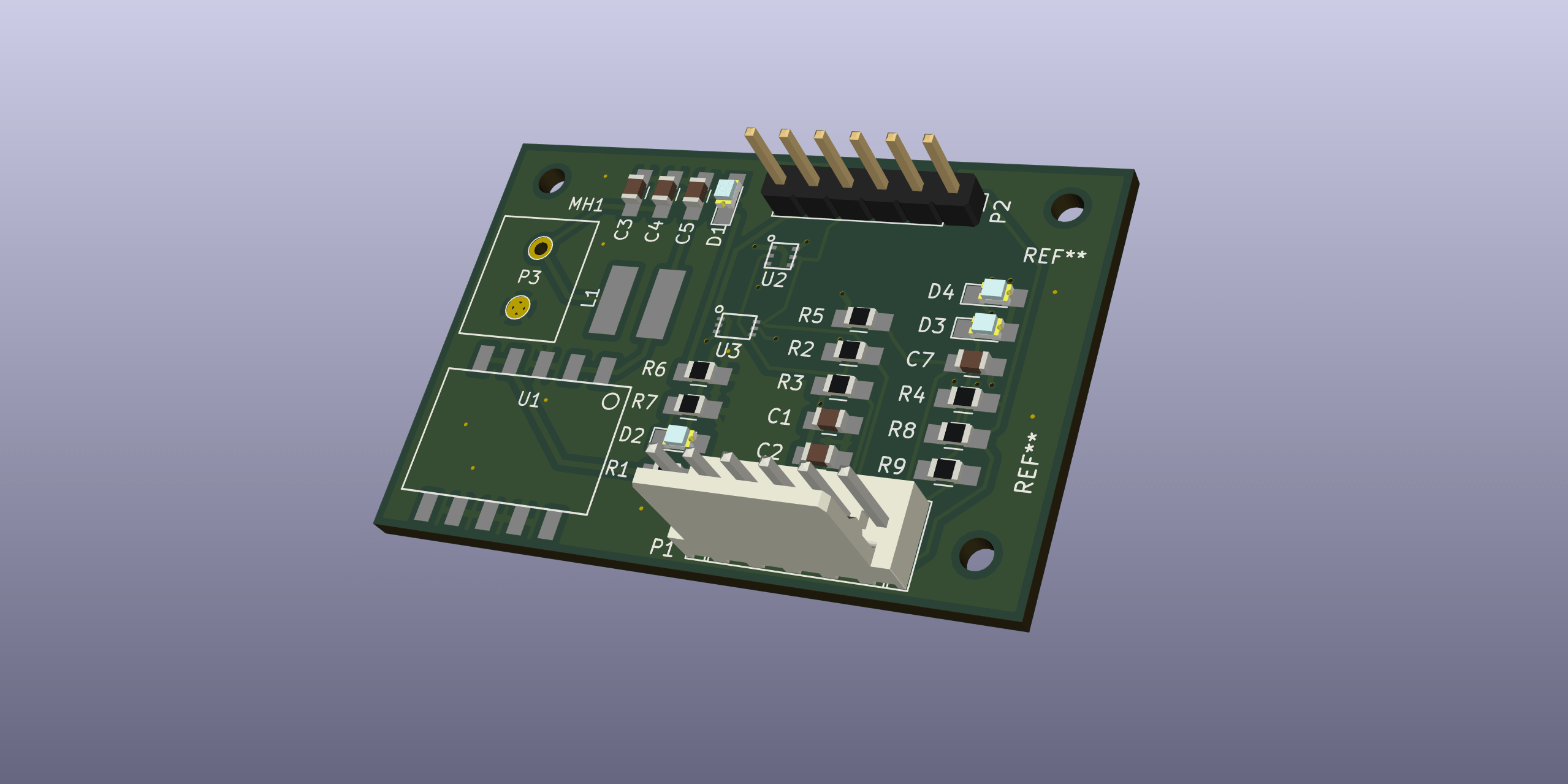
PCB Rendering
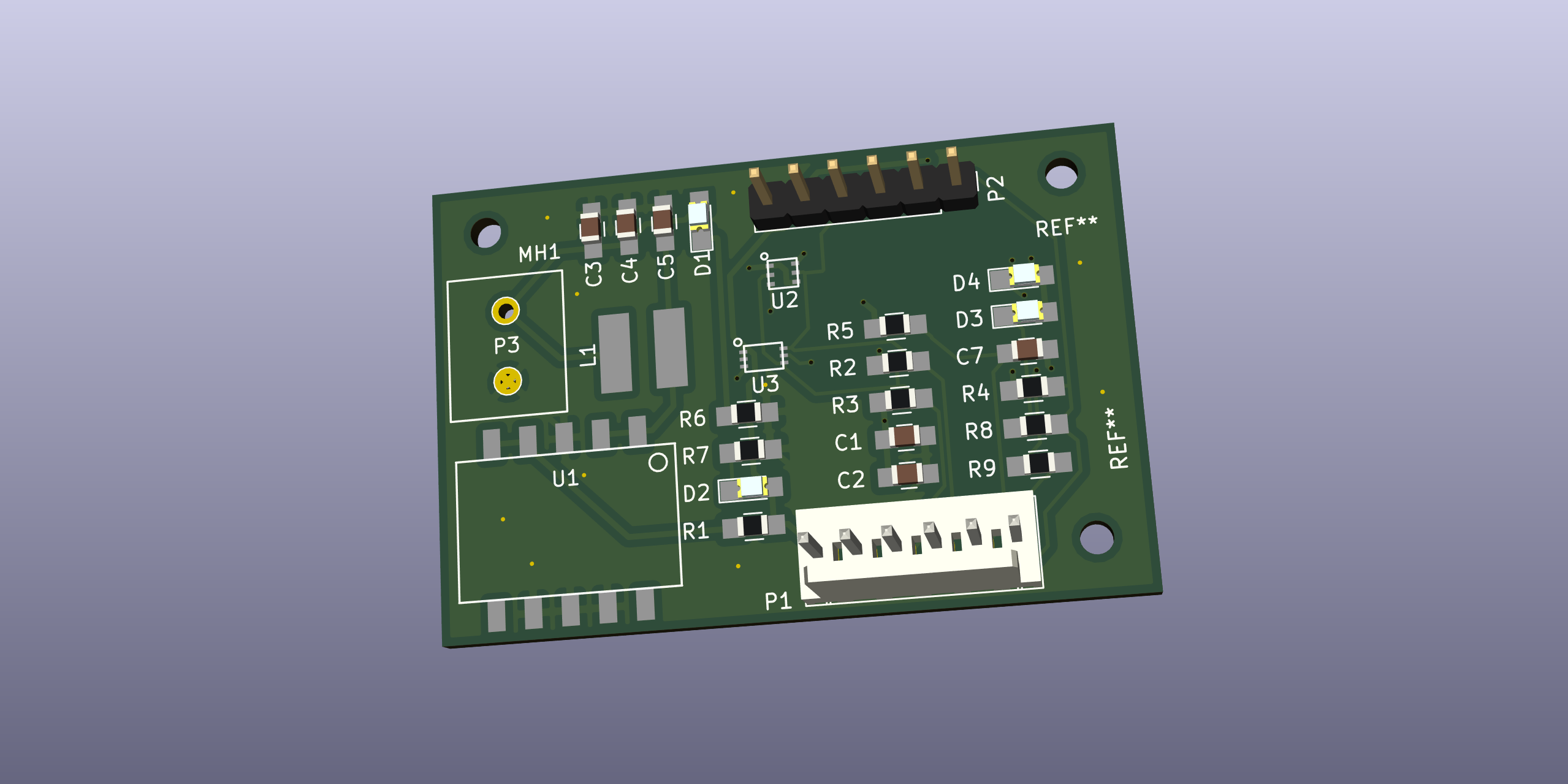
The above shows a 3D rendering from KiCad of what the circuit board looks like once manufactured and assembled.
Procurement Issues
In the design detailed previously, a voltage regulation circuit based on the STR series switching regulator was included. This switching regulator balances high efficiency with a wide range of voltage inputs suitable for a solar panel as an input voltage source. However, due to availability issues we were unable to source the parts for and assemble this part of the circuit.
In our design process, we made sure to submit the control module PCB for manufacture last, so that we could include any additional small circuits that were needed, not initially recognised and highlighted by unit testing of the light sensor and flow modules. This allowed us to integrate two voltage regulation circuits into the control board, to provide both a 5V and a 3.3V supply rail, using the TR series switching regulator, the through-hole variant of the component originally chosen. The 3.3V supply could then be passed to the light sensor module via the Molex connectors.
Light Sensor Devices
BH1750
The BH1750 was chosen as one of our light sensor devices as it is reasonably widely available and used, with various breakout boards and tutorials/demonstrations using the chip being available online. Most importantly, the chip is readily available via UK suppliers including Farnell and RS Online. Our software for interacting with the BH1750 was based on a fork of a publicly-available GitHub repository containing an Arduino library for the chip.
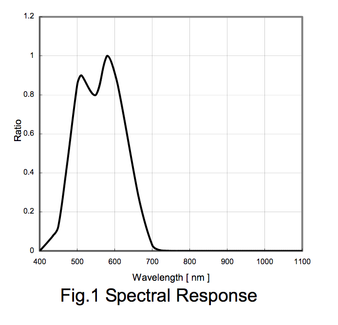
The BH1750 has a single response mode, with the spectral response of the sensor to various wavelengths of light illustrated above. The sensor responds primarily in the 400-700nm range, which roughly matches the wavelength range of the photocatalyst. However, its relative response strength is quite variable within that range, when in reality a more uniform response would potentially be desirable. The response curve is designed to roughly match the human eye, for applications such as dimming mobile device screens or keyboard backlights for battery preservation. However, the photocatalyst's response does not match the human eye.
VEML6030
The VEML6030 has two different response modes, referred to by the VEML6030 Application Note as the ambient light sensor (ALS) channel and the white channel. The software for interacting with the VEML6030 was also based on an Arduino library from a fork of a public GitHub repository.
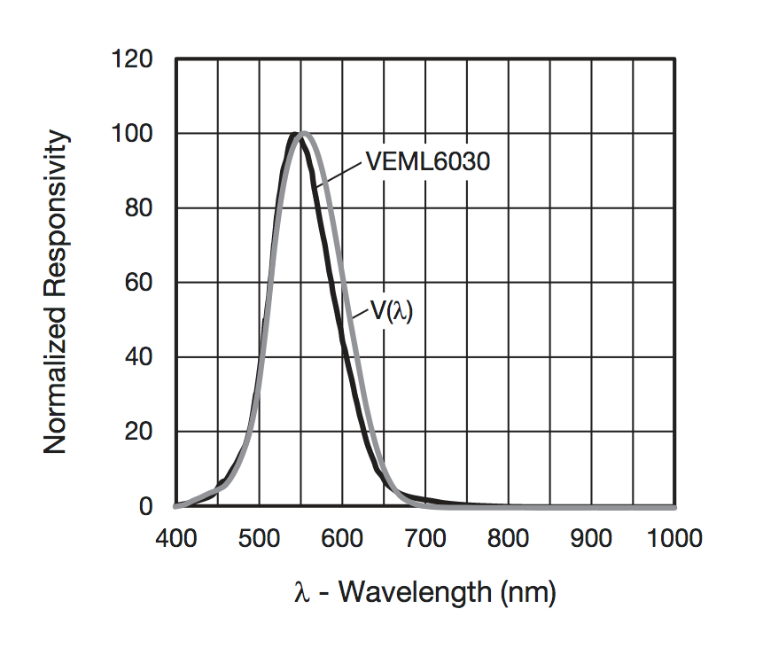
The ALS response curve is plotted in the figure above, along with the approximate response curve of the human eye. Note the similar wavelength range and response curve shape to that illustrated in the evaluation of the BH1750.
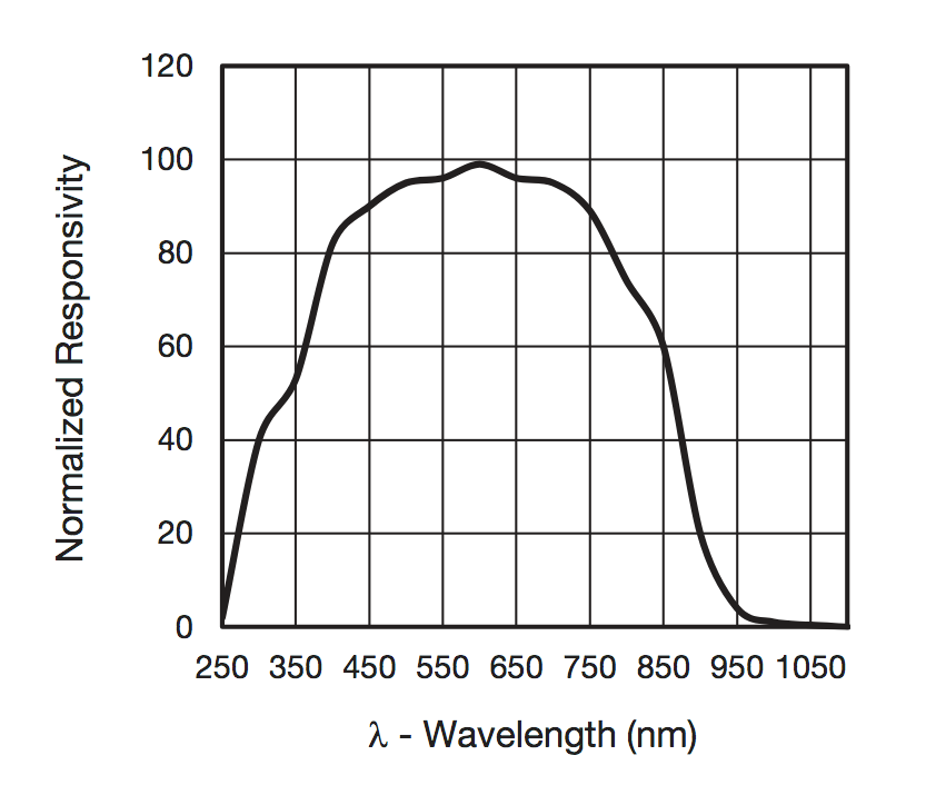
The VEML6030 offers increased flexibility in the sense it offers a second mode, referred to as the white channel. This has a much wider 250-1000nm wavelength range and a much more uniform response in the 350-700nm range required for the application. The shape of the response curve is shown in the above figure.
Design Parts List
The following table lists the parts used during the design process, and their associated costs. This is not necessarily reflective of a per-unit module cost, either for a production or testing model.
| Part Description | Part Number | RS Online Order Code | Farnell Order Code | Appropriate Supplier | Price/Unit (£) | Minimum Order | Desired Quantity | Total Cost |
|---|---|---|---|---|---|---|---|---|
| Ambient Light Sensor | VEML6030 | 122-6787 | 2627811 | Farnell (Order Quantity) | 1.02 | 5 | 5 | 5.1 |
| Ambient Light Sensor 2 | BH1750 | - | 2421284 | Farnell (Order Quantity) | 2.15 | 5 | 5 | 10.75 |
| UV Light Sensor | VEML6075 | - | 2523611 | Farnell | 1.74 | 1 | - | - |
| 10R Resistors | MCWR08X10R0FTL | - | 2447556 | Farnell (Order Quantity) | 0.0057 | 10 | 10 | 0.057 |
| 10uF Capacitors | GRM21BR71A106KA73L | - | 2611944 | Farnell (Order Quantity) | 0.147 | 5 | 5 | 0.735 |
| 100nF Capacitors | 08051C104K4T2A | - | 1833888 | Farnell (Order Quantity) | 0.158 | 10 | 20 | 3.16 |
| 4.7k Resistors | MCWR08X4701FTL | - | 2447672 | Farnell (Order Quantity) | 0.0057 | 10 | 10 | 0.057 |
| Green Power Indicator LEDs | HSMG-C170 | 435-6767 | 5790852 | Farnell | 0.241 | 5 | 6 | 1.446 |
| 470R Resistors | MCWR08X4700FTL | - | 2447662 | Farnell (Order Quantity) | 0.0057 | 10 | 10 | 0.057 |
| | - | - | - | - | - | - | Total | 21.362 |
Testing
During testing, we relied on various open source libraries. Each one was forked into our organisation's GitHub namespace so that they could be easily accessed later. The original repositories for the BH1750 library and VEML6030 library are easily accessible on GitHub and are actively maintained.
The method we used to verify whether the module was working was to connect an Arduino to the board's Molex or debug header and to run an I2C scan, using the i2cdetect library, a third library. This is also available via GitHub, and a fork is available in our GitHub namespace. It is not currently actively maintained, but this is not really necessary for this simple test. The I2C scan verifies that the two light sensor devices are addressable. The sketch is given below:
#include <Wire.h>
#include <i2cdetect.h>

void setup() {
  Wire.begin();
  Serial.begin(9600);
  Serial.println("i2cdetect example\n");
  Serial.print("Scanning address range 0x03-0x77\n\n");
}

void loop() {
  i2cdetect();  // default range from 0x03 to 0x77
  delay(2000);
}
The output to the serial port from the Arduino should look like this for our development board. The VEML6030 is addressable at I2C address 0x10, and the BH1750 at address 0x5c.
i2cdetect example
Scanning address range 0x03-0x77

     0  1  2  3  4  5  6  7  8  9  a  b  c  d  e  f
00:          -- -- -- -- -- -- -- -- -- -- -- -- --
10: 10 -- -- -- -- -- -- -- -- -- -- -- -- -- -- --
20: -- -- -- -- -- -- -- -- -- -- -- -- -- -- -- --
30: -- -- -- -- -- -- -- -- -- -- -- -- -- -- -- --
40: -- -- -- -- -- -- -- -- -- -- -- -- -- -- -- --
50: -- -- -- -- -- -- -- -- -- -- -- -- 5c -- -- --
60: -- -- -- -- -- -- -- -- -- -- -- -- -- -- -- --
70: -- -- -- -- -- -- -- --
This verifies that the two light sensor devices are working correctly. The next step is to use the two libraries for each device, linked to previously. The following sketch based on an example from its library prints light measurements from the VEML6030 to the serial:
#include <VEML6030.h>

VEML6030 ALS;

void setup() {
  Serial.begin(38400);  //Begin Serial
  ALS.begin(0x10);  //Begin the UV module
}

void loop() {
  ALS.AutoRange(); //Determine the best gain and integration time values for given light intensity
  delay(1000); //Wait for new value to be taken, up to 1 second
  Serial.print("Lux = ");
  Serial.print(ALS.GetLux());  //Get compensated UVA value
  Serial.print(" White = ");
  Serial.print(ALS.GetWhite());  //Get compensated UVB value
  Serial.print(" Ambient Raw = ");
  Serial.println(ALS.GetALS());
  delay(1000);
}
The following sketch, again based on its library, performs a similar test for the BH1750:
/*
  Example of BH1750 library usage.
  This example initialises the BH1750 object using the default high resolution
  continuous mode and then makes a light level reading every second.
  Connection:
    VCC -> 3V3 or 5V
    GND -> GND
    SCL -> SCL (A5 on Arduino Uno, Leonardo, etc or 21 on Mega and Due, on esp8266 free selectable)
    SDA -> SDA (A4 on Arduino Uno, Leonardo, etc or 20 on Mega and Due, on esp8266 free selectable)
    ADD -> (not connected) or GND
  ADD pin is used to set sensor I2C address. If it has voltage greater or equal to
  0.7VCC voltage (e.g. you've connected it to VCC) the sensor address will be
  0x5C. In other case (if ADD voltage less than 0.7 * VCC) the sensor address will
  be 0x23 (by default).
*/

#include <Wire.h>
#include <BH1750.h>

BH1750 lightMeter(0x5c);

void setup(){
  Serial.begin(9600);
  // Initialize the I2C bus (BH1750 library doesn't do this automatically)
  Wire.begin();
  // On esp8266 you can select SCL and SDA pins using Wire.begin(D4, D3);
  lightMeter.begin();
  Serial.println(F("BH1750 Test begin"));
}

void loop() {
  uint16_t lux = lightMeter.readLightLevel();
  Serial.print("Light: ");
  Serial.print(lux);
  Serial.println(" lx");
  delay(1000);
}
A table of typical lux values for various light sources can be found in the design guidelines for the VEML6030, but is reproduced below.
| Luminance | Example |
|---|---|
| 1 lx | Full moon overhead at tropical latitudes |
| 3.4 lx | Dark limit of civil twilight under a clear sky |
| 50 lx | Family living room |
| 80 lx | Hallway/bathroom |
| 100 lx | Very dark overcast day |
| 320 lx to 500 lx | Office lighting |
| 400 lx | Sunrise or sunset on a clear day |
| 1000 lx | Overcast day; typical TV studio lighting |
| 10 000 lx to 25 000 lx | Full daylight (not direct sun) |
| 32 000 lx to 130 000 lx | Direct sunlight |
Recommendations
Component Selection
As described in the previous section where the two light sensor devices we used were compared, the idea is to find a light sensor that matches the responsivity of the photocatalyst as closely as possible. A sensor device with a 'white channel' mode is well-suited to this purpose, as most light sensor devices are calibrated to have a responsivity profile that approximates that of the human eye for use in dimming mobile phone screens or setting the backlight of a keyboard.
The white channel response curve for the VEML6030 is reproduced below. This has good responsivity across all possible wavelengths that the photocatalyst responds to. Any light sensor device with a similar response profile would in theory work equally well. It is also important to select a device that communicates the light level over I2C, which is a digital communication protocol, as this is how the rest of the system has been setup. Also, this makes any light sensor device compatible with the same debugging tools described in the testing section.
Bill of Materials
This is a rough final per-unit bill of materials for a production or testing module. This is to give an idea of per-unit cost of this individual sub-module, and its contribution to the overall cost of the system. The assumption is made that the VEML6030 is the chosen light sensor device and that the voltage regulation circuit is moved to the control module as recommended.
| No | Desceiption | Model | Value | Quantity | Price/Unit | - |
|---|---|---|---|---|---|---|
| 1 | Unpolarized capacitor | C | 100nF | 1 | 0.158 | 0.158 |
| 2 | Unpolarized capacitor | C | 10uF | 1 | 0.147 | 0.147 |
| 4 | Green Power Indicator LEDs | HSMG-C170 | LED | 3 | 0.241 | 0.723 |
| 7 | 6 pin connectors | CONN_01X06 | MOLEX_01X06 | 1 | 0.671 | 0.671 |
| 8 | 2 pin connectors | CONN_01X02 | TERM_01X02 | 1 | 0.45 | 0.45 |
| 9 | Resistor | R | 10R | 1 | 0.0057 | 0.0057 |
| 10 | Resistor | R | 10k | 1 | 0.0057 | 0.0057 |
| 11 | Resistor | R | 4.7k | 2 | 0.0057 | 0.0114 |
| 12 | Resistor | R | 470R | 3 | 0.0057 | 0.0171 |
| 13 | Ambient Light Sensor | VEML6030 | VEML6030 | 1 | 1.02 | 1.02 |
| 14 | Circuit Board Manufacture (Prototyping Costs) | - | - | 1 | 1.3666666666666665 | 1.3666666666666665 |
| - | - | - | - | - | Total | 4.575566666666667 |